OSN 9800 P32 subrack is an ultra-large capacity all-optical cross-connect product. It is mainly used at the backbone core layer and metro aggregation layer. It works with the OSN 9800/1800 to build a complete E2E WDM/OTN backbone transmission solution, achieving transparent and ultra-large capacity transmission.
View Overview of Huawei Transmission Network Hot Series
1 to 32-degree reconfigurable optical add/drop multiplexer (ROADM)
Electrical
N/A
Max. number of wavelengths
Fixed grid: 96 wavelengths @50 GHz grid
Flex grid: The maximum number of wavelengths is related to the width of the flex channel.
Product Details
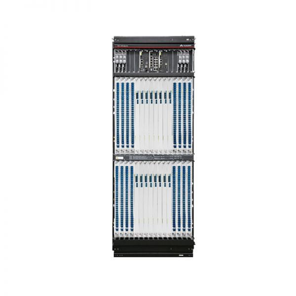
Huawei OptiX OSN 9800 P32 Chassic:
Subrack Areas and Slots
Boards need to be installed in the designated slots in a subrack. The subrack runs on -48 V DC or -60 V DC.
The equipment includes the following areas: the power supply, system control, optical supervisory, and interface area, fan area, fiber routing area, and service board area.PIU boards are located in the power supply, system control, optical supervisory, and interface area. If an area has the same background color as a PIU board, the PIU board powers the boards located in this area.
Figure 1. Schematic diagram of the areas and slots in the OptiX OSN9800 P32subrack
Table 2 shows Descriptions of the areas and slots in the OptiX OSN9800 P32subrack.
Area
Composition
Slot
Function
Power supply, system control, optical supervisory, and interface area
6 PIU boards (PIU)
2 CTU system control boards (TMP1CTU)
1 EFI board (TMP1EFI)
1 spectrum analyzer boards (TMP1MON32)
PIU: IU100-IU102, IU110-IU112
CTU: IU105, IU107
EFI: IU106
MON32: IU108-IU109
Reserved slots: IU103-IU104
The PIU boards are in mutual backup. Therefore, the failure of any power input to the equipment does not affect the normal operation of the equipment.
NOTE:
The PIU boards on the left and right sides of the EFI board are in mutual backup, for example, the PIU boards in slots IU100 and IU110, the PIU boards in slots IU101 and IU111, and the PIU boards in slots IU102 and IU112.
The system control boards are configured in 1+1 backup mode. The system control board manages and provides a clock to all other boards in the equipment. It also provides for inter-NE communication.
The EFI board provides maintenance and management interfaces.
The MON32 board detects the insertion loss between the board and the backplane and detects the single-wavelength optical power of optical signals in line directions.
Fan areas
2 fan tray assemblies (TMP1FAN)
Lower portion: IU90
Upper portion: IU91
The fan tray assemblies are used to ventilate the equipment.
Fiber-routing areas
4 fiber troughs
N/A
Fiber patch cords connecting to boards are routed to the left or right side of the equipment through the upper- and lower-side fiber troughs.
Service board areas
32 service boards
Lower portion: IU1�CIU16
Upper portion: IU17�CIU32
Service boards need to be configured based on the service plan and all of them are installed in the two service board areas.
Requirements for Inserting Service Boards in a Subrack
To ensure that service grooming is normal and fiber routing is convenient, service boards must be inserted into the subrack in accordance with certain requirements.
To insert service boards into the9800 P32subrack, the following requirements must be met:
● The sequence of installing optical tributary boards is D->C->B->A. That is, you can insert boards in the next area only after all slots of area D are fully inserted with boards.
● The sequence of installing optical line boards is A->B->C->D. That is, you can insert boards in the next area only after all slots of area A are fully inserted with boards.
When the preceding board installation sequence is met:
● Because there are a large number of optical fibers on the front panels of optical tributary boards, to facilitate future expansion using optical fibers, install the optical tributary boardsfrom edge side to the middlein sequence. Example: During the installation in area D, if there are two OT3232 optical tributary boards, you need to select the area with the most convenient fiber routing according to the actual environment. Assume that the left-side area D is selected. Preferentially use slots IU1 and IU2, and then use slots IU3 and IU4 in sequence. Assume that the right-side area D is selected. Preferentially use slots IU16 and IU15. Other areas comply with the same rules.
● Because there are a few optical fibers on the front panels of optical line boards, install the optical line boards in each areafrom left to right. Example: If there are three optical line boards, preferentially install the three optical line boards in slots IU5-IU7 of area A from left to right in sequence. If new optical line boards need to be installed, install them from left to right in sequence until area A is full. Other areas comply with the same rules.
NOTE:
Slots D and C on the left and right sides are the same. There is no requirement on the sequence of installing boards in the two slots.
Figure 2. Slots for installing service boards in the OptiX OSN9800 P32subrack
NOTE:
The cable trough in the middle of the subrack is printed with the requirements for inserting service boards.
Get More Information
Do you have any question about the Huawei OptiX OSN 9800 P32
Contact us now via Live Chat or Contact@huatenmax.com.
Specification
Huawei OptiX OSN 9800 P32 Specifications
Subrack dimensions (mm)
1390 (H) x 496 (W) x 315 (D) (without cabinet)
Suitable cabinet
ETSI 300 cabinets, such as A63B
Number of slots for service boards
32
Switching capability
Optical
1 to 32-degree reconfigurable optical add/drop multiplexer (ROADM)
Electrical
N/A
Max. number of wavelengths
Fixed grid: 96 wavelengths @50 GHz grid
Flex grid: The maximum number of wavelengths is related to the width of the flex channel.
Channel spacing
Fixed grid: 50 GHz grid/100 GHz grid
Flex grid: Supports channel spacing designs, and the minimum can be set to 6.25 GHz.
Follow us, you will get the latest products and industry information in our insights emails. Subscribe now also can get more than 50 valuable white papers. Learn Details>>>